Shape and connectivity
The Overture transportation theme captures the physical shape and connectivity of the transportation network through the interaction of the theme's two feature types: segments and connectors.


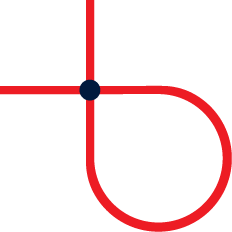
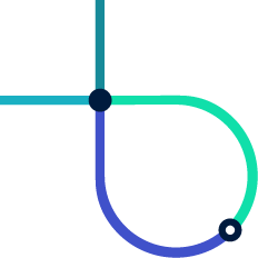
A connector physically joining three segments.
Connectors
The connector feature type carries point geometry which describes a location where a physical connection between two or more segments occurs (or may occur in the future).
Connectors have no properties apart from geometry and standard Overture feature properties. All other aspects of the transportation theme are modeled on segments.
Segments
The segment feature type carries LineString geometry which describes the physical shape of a section of the transportation network. A segment may represent an entity with a
tangible real-world existence, such as a paved road; or it may represent
an intangible entity, such as a ferry route, which has a well-known
shape but no observable presence in the real world.
Physical connectivity
Two or more segments are physically connected at a given connector if each segment's connectors property contains a reference to the connector.
The connector geometry's coordinates should preferably be contained within the segment geometry's coordinates, in which case the connector coordinates define the point of physical connection. This constraint will always be met by official Overture data releases. Where this is not possible, the point of physical connection is the closest point to the connector coordinates which intersects the segment geometry.
Conversely, two segments are not physically connected if their connectors properties do not reference a shared connector, even if their geometries overlap or even share a coordinate in common.
Travel from a point on one segment to a point on another physically-connected segment is allowed, unless limited by an explicit restriction such as an access or turn restriction.
All segments in official Overture transportation data releases have a minimum of two connectors, one at each end of the geometry, even if those endpoint connectors are not attached to any other segment. This is not a mandatory minimum and is not enforced by the schema. It is done to allow new segments to connect into the existing network without needing to change the properties of existing segments.
Start, end, and orientation
The first coordinate in a segment's geometry is the start of the segment and the last coordinate is the end. A segment is oriented away from the start and toward the end. The examples below show two segment geometries with identical coordinates, oriented in opposite directions.
type: LineString
coordinates:
  - [1, 0]   # Start
  - [0, 0]
  - [-1, 0]  # End


This segment geometry is oriented due west.
type: LineString
coordinates:
  - [-1, 0]  # Start
  - [0, 0]
  - [1, 0]   # End


This segment geometry is oriented due east.
Heading
Travel along a segment's geometry can follow one of two possible headings: forward or backward. The forward heading proceeds toward the end of the segment; while the backward heading proceeds back toward the start of the segment.


Travel heading along a segment.
Directionality
🚧 We are developing a segment-level directionality concept similar to lane directionality to indicate what travel headings are allowed or prohibited along the segment. This effort is ongoing, so please check back soon.
Sub-types
Segment features have a subtype property whose value gives more
specific information about the segment's role within the transportation
network.
The subtype property may be one of road, rail, or water but
only road is currently well defined. A road segment models any kind
of road, street, or trail, including a dedicated path for walking,
cycling and similar activities. For more information about road segments, see the page on roads.
Level (Z-order)
Segment geometry is two-dimensional. In the real, 3D, world, however the entities represented by segments can be above or below each other, as may happen with tunnels, bridges, overpasses, and stacked multi-level highway interchanges. To accurately render top-down 2D maps, it is important to know the relative stacking order, or Z-order, of segments.
Segment Z-order is given by the level property. A level value of
0 indicates visual level, with positive numbers indicating above
visual level, negative numbers indicating below visual level, and in
general, a lesser number indicating a lower position in the stacking
order than a greater number.
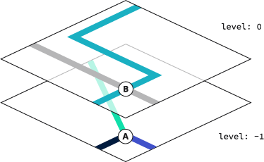
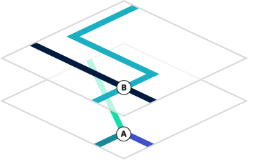
Ground level segments stacking above tunnel segments.
Note that two segments with different level values may be physically
connected, since level is an approximation for rendering and is not
meant be a precise indication of elevation at different points along the
segment. Connectors do not have a level.
Segmentation
The term segmentation describes the process of converting upstream source data into Overture transportation shape and connectivity data modeled as segments and connectors.
Shape stability
A primary goal of Overture's segmentation process is to promote stability of segment shape across Overture data releases. For example, if a certain real-world stretch of Main Street is represented by a single segment with particular geometry in release 1, we will strive to avoid slicing the exact same geometry up into two, three, or four segments in release 2.
Note that aiming for segment shape stability categorically does not mean that Overture aims for a stable transportation dataset. On the contrary, we aim to continuously improve data accuracy and coverage, and expect the transportation network dataset to constantly evolve and grow as a result. Our goal is simply to minimize unnecessary, semantically meaningless, changes in how the geometry is sliced into segments across data releases.
Several features of the transportation theme schema were designed to allow the segmentation process to achieve its segment stability goal. These features include:
- interior connectors.
- geometrically scoped segment properties.
Overture ID stability
Overture pursues shape stability to improve the ability to assess whether two segments from different points in time (or from different upstream data sources) represent the same real world entity. Overture's success at this assessment directly feeds into the stability and precision of Overture IDs assigned to segments. In turn, higher Overture ID stability and precision makes transportation theme data more useful for conflation.
Interior connectors
A key feature of the Overture transportation schema which enables shape stability is the ability of segments to support connectors at interior positions along their geometry, not only at their endpoints. The ability to add internal connectors prevents the segmentation process from having to blindly follow every split or join introduced in upstream source data.
For example, imagine a square city block bordered by road on all four sides has been mapped in the source data, but a back alley dividing the block along the east-west axis has not. If the back alley is subsequently mapped in the source data, the Overture segmentation process can connect to the transportation network without having to subdivide any existing segments by simply introducing internal connectors on the north-south road segments bordering the block to the east and west. As a result, the Overture IDs of the north-south road segments remain as they were and no data needs to be re-conflated.
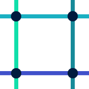

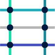
A square city block bordered by four roads before (left) and after (right) mapping the back alley using internal connectors.
Note that in the above example, an official Overture data release would insert coordinates in the middle of the north-south segments, if they did not already exist, because Overture data releases will always ensure that every segment's geometry includes all of its connectors. From a computer's perspective, this is a very minor alteration of the segment's shape.
Geometric scoping
Many segment properties may include a linear reference so that they apply only to a part of the segment geometry. We refer to these linearly-referenced property values as being geometrically scoped and discuss geometric scoping at greater length in the page on scoped properties.
Geometric scoping allows the segmentation algorithm to avoid introducing segment splits simply because a certain property has different values along different parts of the geometry. Like interior connectors, geometrically-scoped properties enable the segmentation process to make decisions that promote shape stability, ultimately resulting in more precise and stable Overture IDs and less churn in conflated data.


A single segment with multiple geometrically-scoped speed limit values.
Loops
Although it is technically possible to use the Overture schema to express a segment forming a connected loop, such loops are considered invalid and will never be produced by the segmentation algorithm.
An illegal loop where one of a segment connects to the other end can be corrected by splitting the segment and introducing a second connector to maintain physical connectivity. An illegal self-crossing loop of degree N can be corrected by splitting the segment into N pieces.


An illegal loop connected at its endpoints (left) and a possible correction (right).


An illegal self-crossing loop (left) and a possible correction (right).